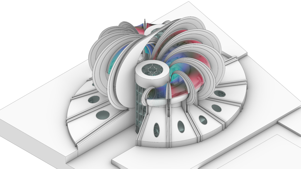
Since we decided that our first case study would have been the Osaka pavilion, we started researching the project documentation, which was unfortunately lacking in details since the project never made it beyond the competition. In a 3D model for virtual reality, however, nothing can be left to chance. You can’t use tricks or “dark corners” to hide missing information, as you would probably do for a static render or a video. The visitors must be able to explore the pavilion as if they were actually in the physical space. Everything is out in the open. Likewise, we can’t build the scene as if it were the 3D space of a traditional videogame, where volumes and details of objects are simplified with textures.
This thinking therefore guided our work, but it wasn’t our only consideration. We have to admit that Sacripanti has meanwhile become almost a presence in our lab – we couldn’t have disappointed him.
And so, we imagined ourselves as archaeologists unearthing a building that was never built, re-constructing the Osaka pavilion in 2021, 53 years after its conception.*
*The 3D modeling of the Osaka pavilion has already been addressed by others, but (as far as we know) never with the precise purpose of making the model explorable in VR.
If you haven’t read them yet, please read the introductory articles about Maurizio Sacripanti and the Osaka ’70 competition.
As mentioned, the available documentation does not cover the whole architectural system. Since Sacripanti did not win the competition, he left us a project with a low-medium level of representation of construction detail, making it difficult to interpret several architectural and technological particulars. The drawings are often contradictory and therefore we had to make some necessary decisions affecting the architectural behavior of the project. However, by studying the documents stored in the MAXXI and Fondo Maurizio Sacripanti archives, we had a good baseline from which to start our adventure of reconstructing the pavilion. To these archive sources we added the interviews with some of the protagonists who supported Sacripanti in the design process, such as Maurizio Decina and the architects Laura Thermes and Franco Purini. Finally, some physical models and details – built in our fabrication lab – have helped us to understand the functioning of the dynamic elements of the pavilion.
In an attempt to turn limitations into opportunities, we have taken the chance to define an approach, that can be used on other occasions as well, to build such models:
- The 3D modeling did not follow a straight path. We started with an exploratory model to understand how to manage its complexity. With a trial-and-error strategy, we have defined the guidelines for modeling the advanced versions of the pavilion cleanly and efficiently.
- Since the documentation leaves room for interpretation around several details, we needed to make decisions that would normally belong to an advanced design stage. Trying to respect the original idea of the project, we have therefore performed a re-design.
- The model is made to be displayed with the Oculus Quest headset. Hence, we needed to optimize the model for the VR experience to work properly, i.e. never going under 72 fps. We have thus undertaken a strategy aimed at enabling the VR experience, favoring the architectural quality over photorealistic rendering.
- The 3D modeling has been undertaken with the software Rhinoceros, combined with Grasshopper and the physics engine Kangaroo, for the initial dynamic simulation. The modeling process has been first performed through N.U.R.B.S., which have then been converted into optimized meshes.
- The kinetic elements of the model have then been prepared in Blender in order to create the animation for the VR, such as working on bone settings and vertex weights.
- The final animation has been programmed in Unity via a combination between C# scripts, VPL nodes, and animators.
Understanding the pavilion
Before delving deeper into the reconstruction of the model, let’s briefly describe the main elements of the project based on the documentation in our possession.
The pavilion is divided in two symmetrical parts, one rotated by 180 degrees from the other. The access to the pavilion takes place, through a ramp system, in correspondence of two circular towers. The top of the tower has a continuous opaque closure, which is crowned by a clerestory having a circular pattern. The inner structure of each tower is composed by four hollow concrete columns inside of which is foreseen the passage of the facility systems.
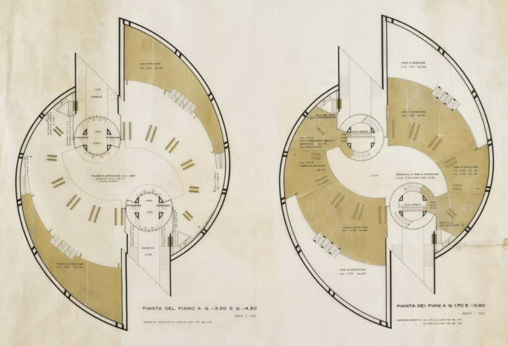
The towers host the main stairs. Two additional systems of stairs (one of which is a system of escalators) guarantee the circularity of the trails. The exhibition routes take place on eight different floors, including a basement floor and two terraces.
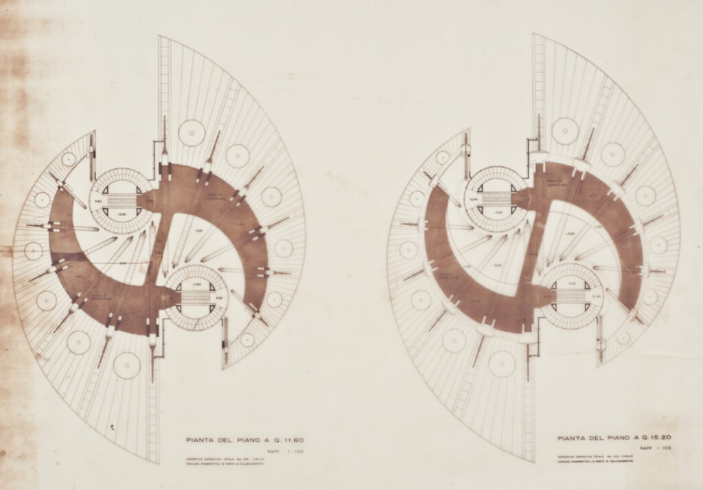
The exhibition hall on the ground floor is marked by seven pairs of steel pillars per side that are arranged along two opposing spirals. The pillars hold up the system composed by the blades and the mantle, which is the most complex and original element of the project.
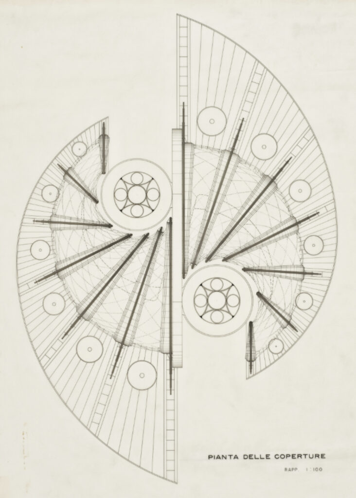
The system of the blades is composed by a “double set of seven circular blades – each one hinged at an eccentric center of gravity – swinging on pivots through a pneumatic system“*. The blades would have to move in a combinatory manner during the whole life of the pavilion. The shape of the blades, combined with the features of their structure, allows for them to always maintain the static balance in each position. Each blade is reinforced with two bottom stiffeners and two upper perpendicular steel wings on which the elastic mantle is hooked.
*Description from the technical report of the original project
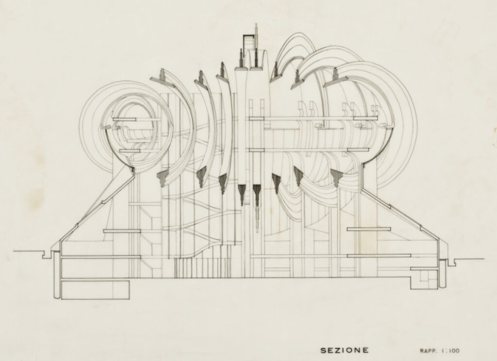
The mantle serves as a cover and it would probably have been painted by Achille Perilli. The mantle can adapt itself dynamically to the swinging of the blades, thus changing in an unpredictable way and reinforcing Sacripanti’s idea of the pavilion as a living form.
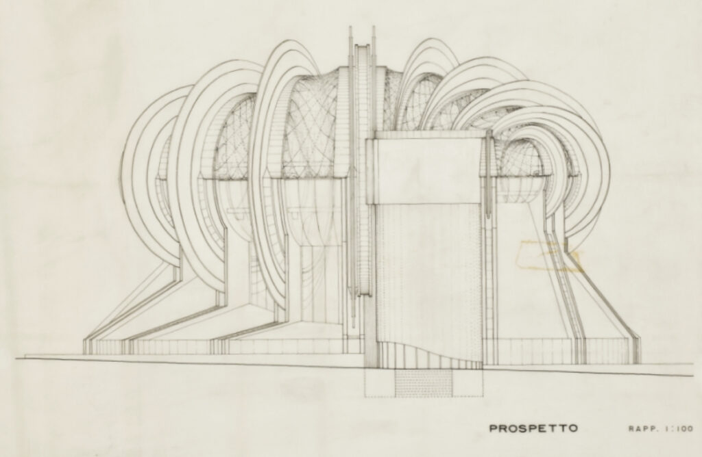
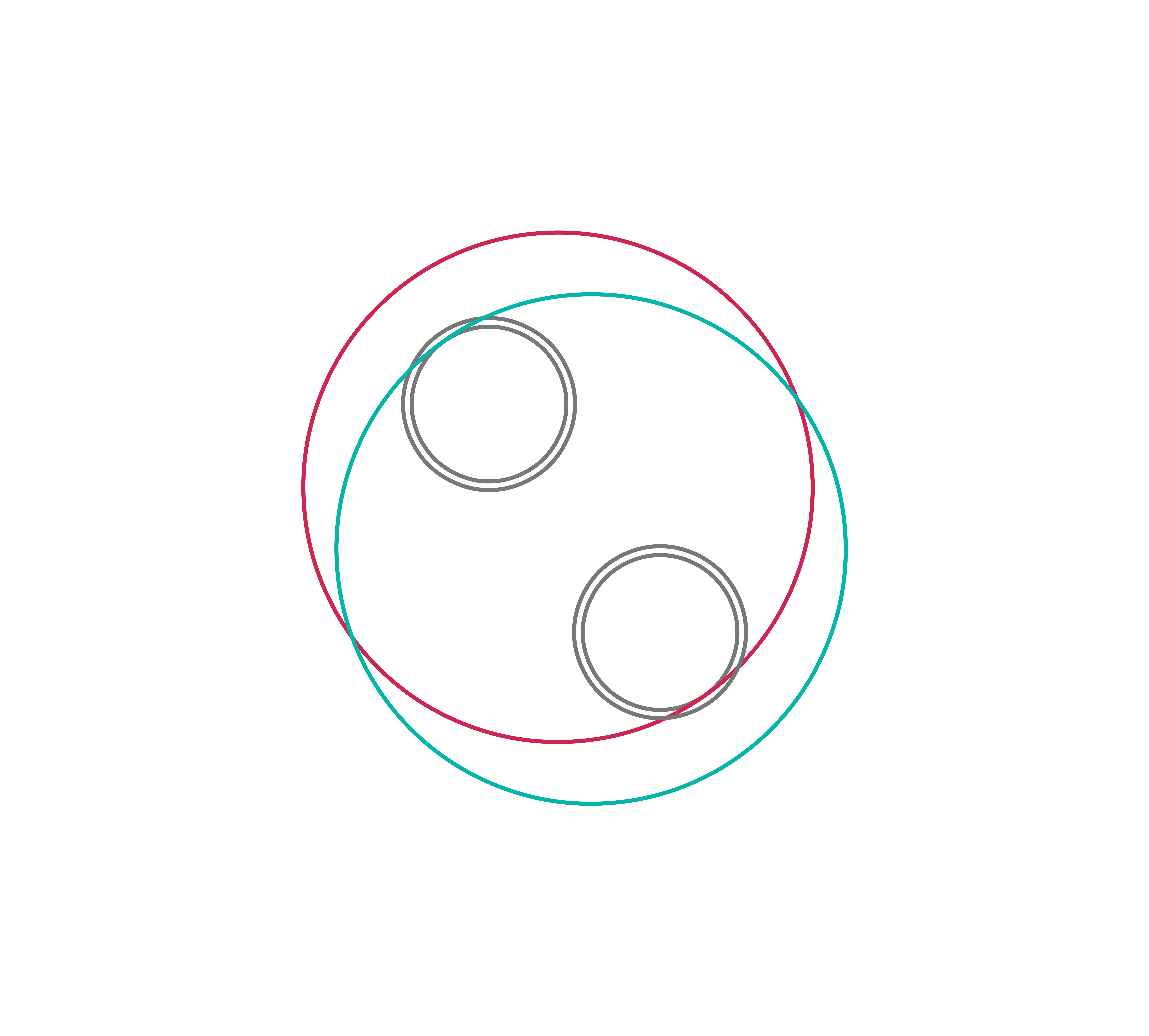
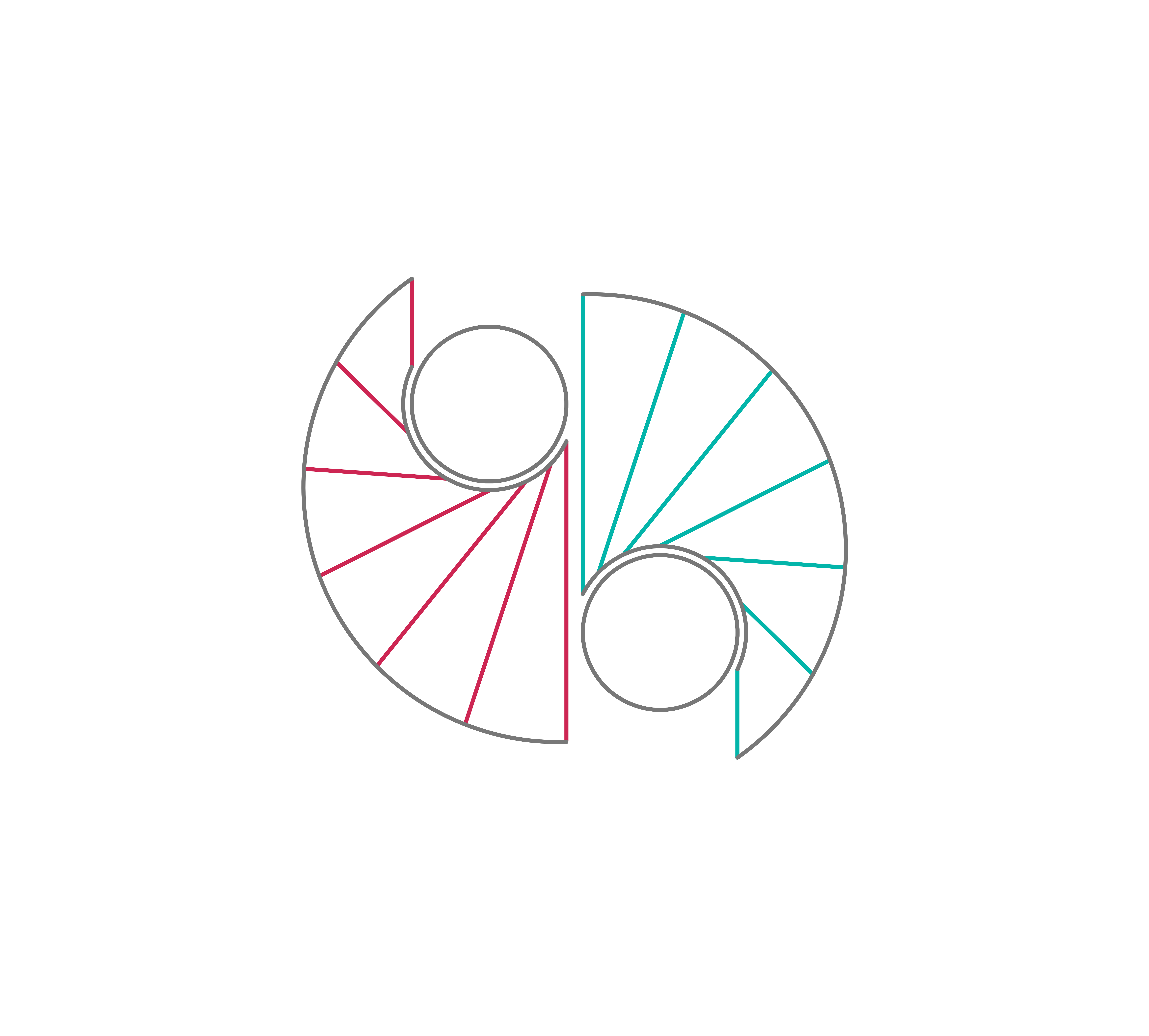
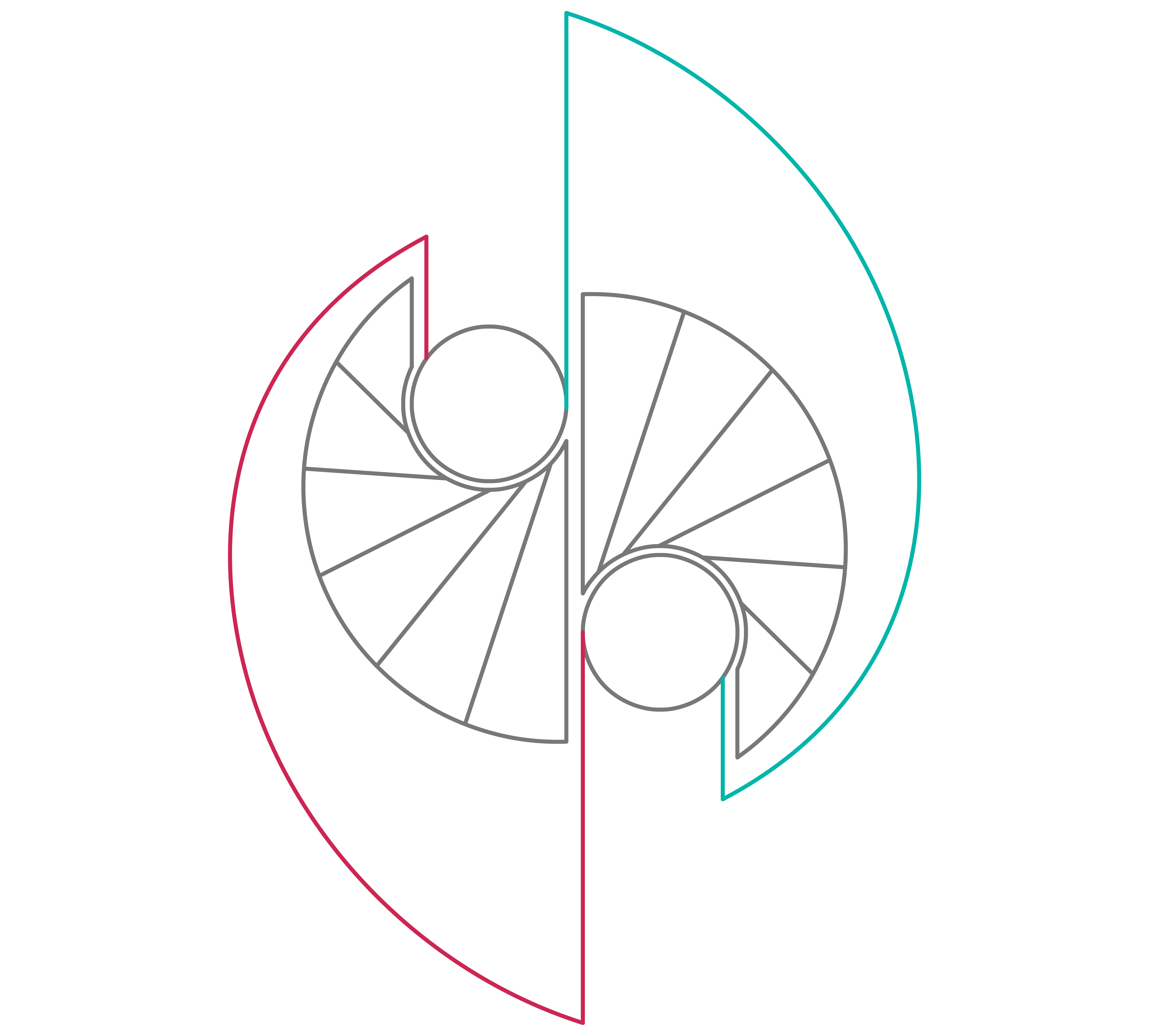
The elements described so far are the fundamental ones of the project. In order to reconstruct the pavilion, we then studied many specific details, evaluating them one by one to adhere as much as possible to the original concept. To maintain the logical and design coherence we have adopted a diagram that has accompanied us during the digital reconstruction:
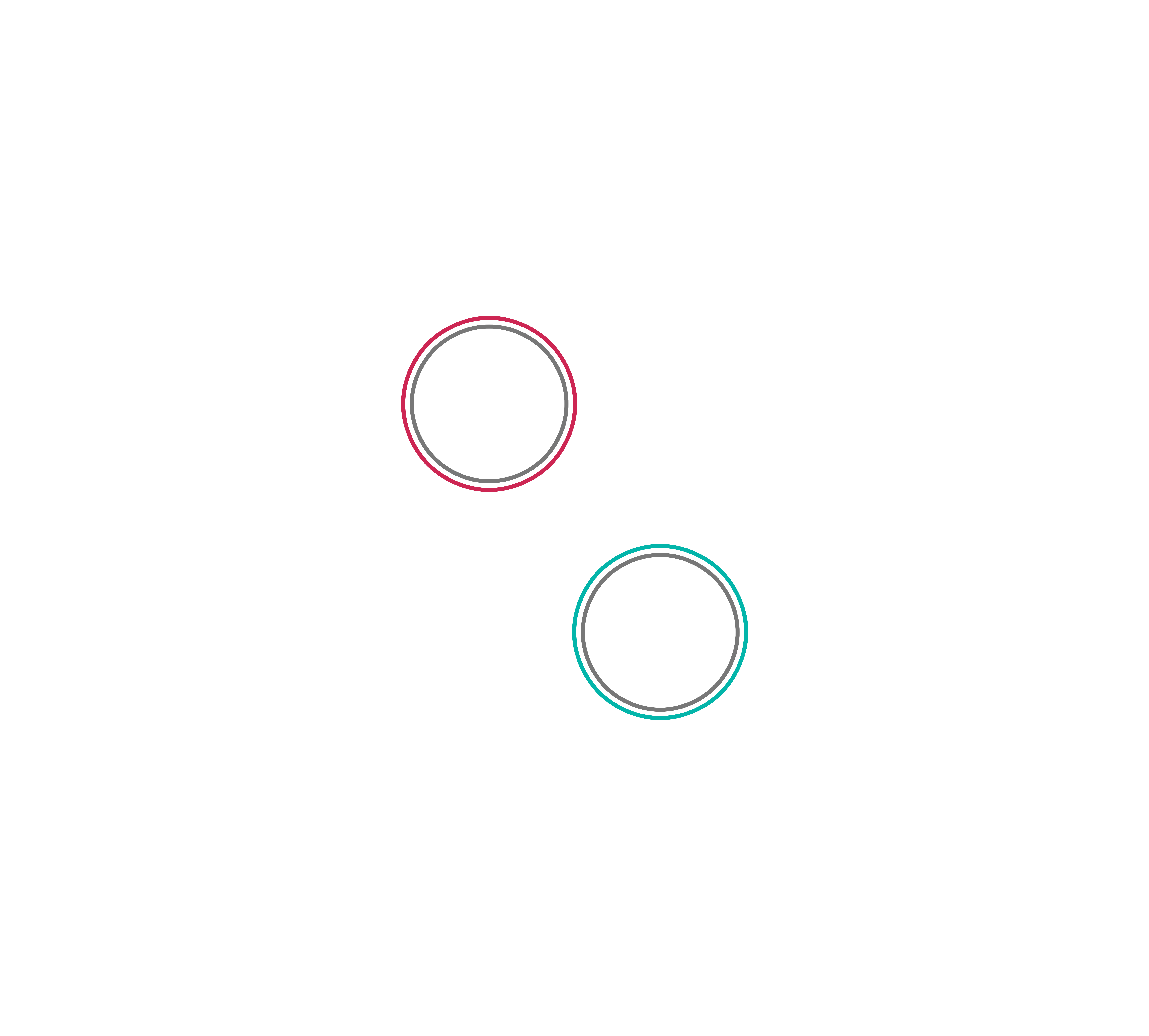
- The two towers have been used as landmarks to reference the two sides of the pavilion.
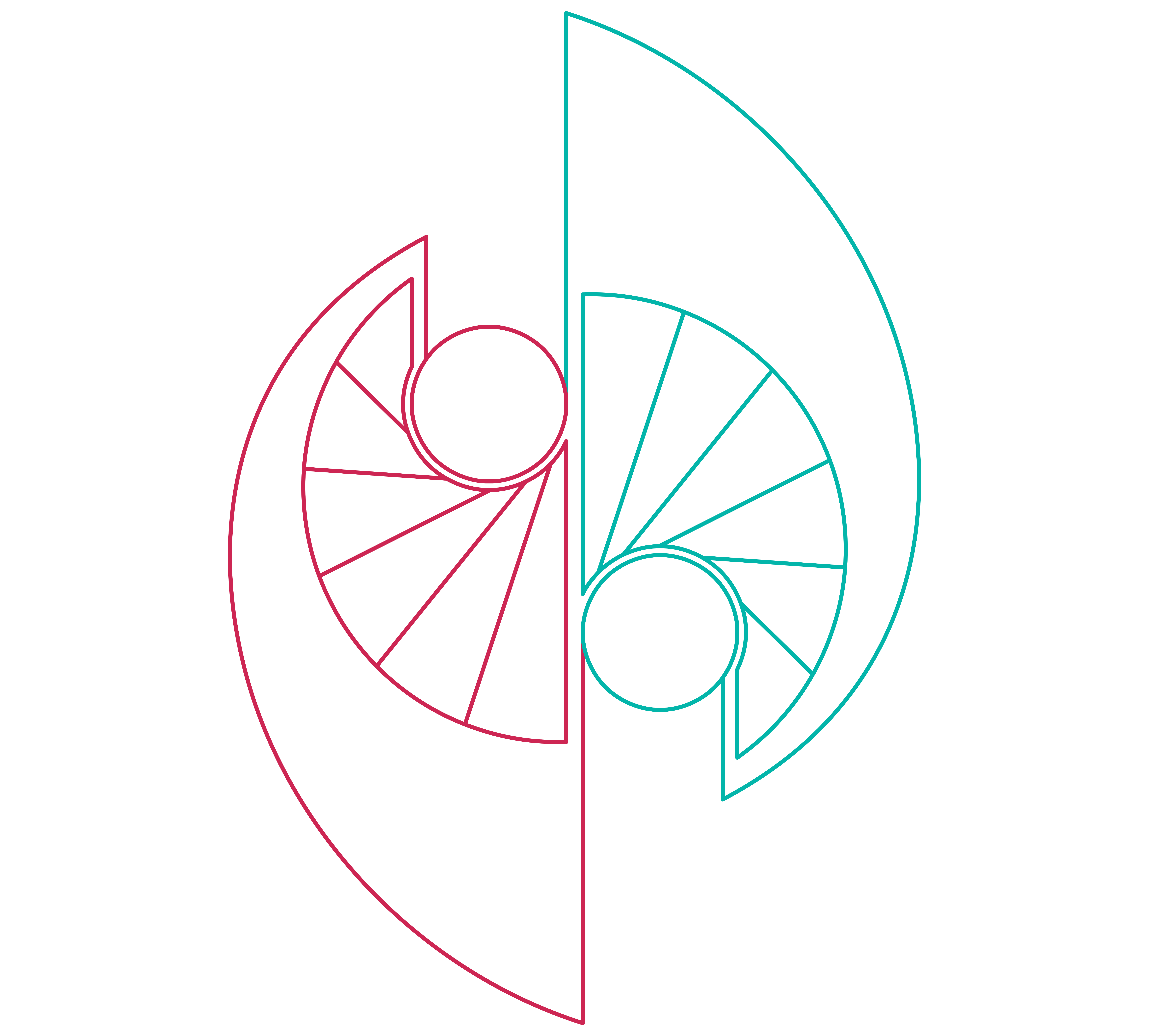
- The inner and outer boundaries of the blades-mantle system are generated from two couples of eccentric circumferences, which are then cut by a couple of lines.
- Inside each resulting shape, a set of seven lines – the axes of the blades – is tracked. Those lines are tangent to the circumferences of the towers.
- The spiral bases of the pavilion are drawn and then bordered by a couple of straight lines.
After the complete reconstruction of the pavilion, we explored it in VR and we discovered that Sacripanti was right, the Osaka pavilion is “a living thing”. From each spot of the galleries, the vision of the internal space changes continuously, the movement of the blades is affecting and meaningful. Exploring the pavilion, it seems almost unnecessary to have an interior layout: one was never designed, and we guess that it should have been as modest as possible so as not to conflict with the breath of this architecture.
Would you like to know how we modeled the pavilion, defining the details and optimizing it for the VR experience? Want to try to rebuild it in Rhinoceros?
Keep reading, here is the path we followed, step by step.
Rebuilding the model*
*Please note: our strategy involves the use of Rhino blocks to simplify the process and to reduce the size of the model. Using blocks allows for the simultaneous modification of the repetitive elements of the pavilion, speeding up the entire process and avoiding errors.

Step 1 – Towers
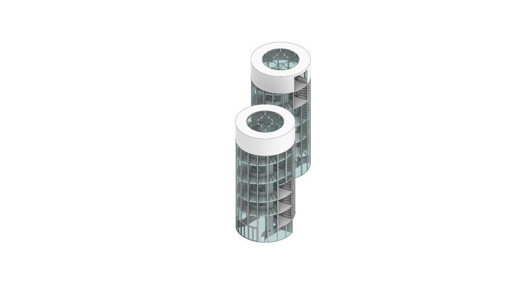
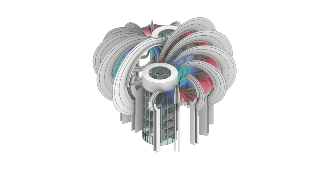
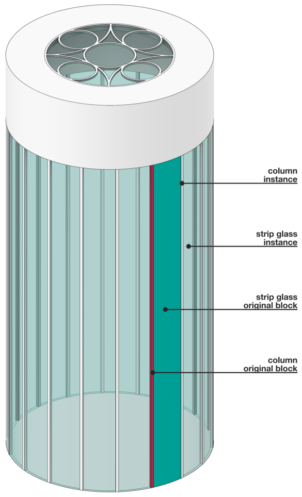
Let’s start the modeling process with the towers, our landmarks, by which we can identify the altitude of each floor. Each tower has a radius of 5.00 m, and its height goes from -3.20 m to +18.70 m. We can break down this base cylinder through 18 squared columns (15 cm per side) and 18 curved glass strips, both reaching a height of + 15.00 m. All these elements are modeled as blocks with the Rhino command Extrude Curve. Then we obtain all the repetitive elements through the Rhino command Array Polar.
The tower is crowned by a cylinder, 15 cm thick, with a hole on the top hosting the clerestory, which is modeled extruding a circular pattern.
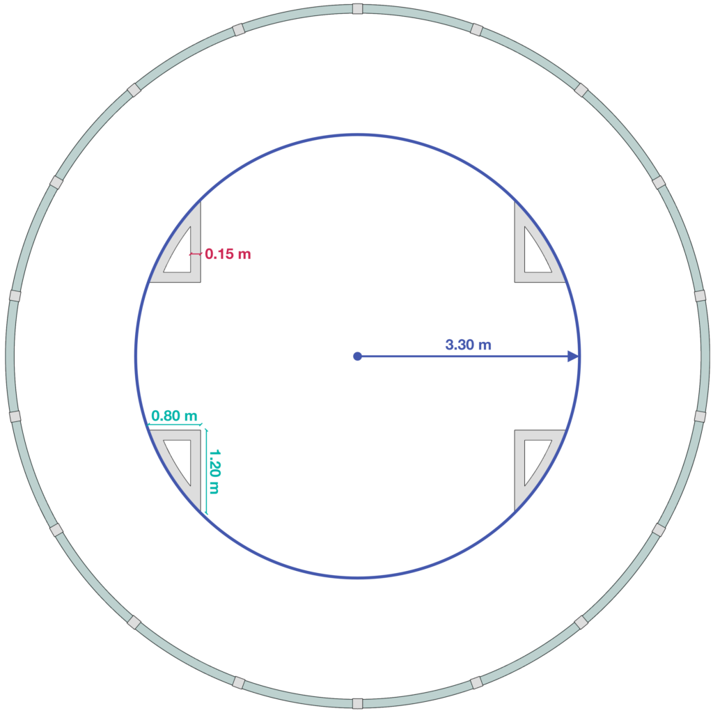
The four hollow columns composing the inner structure are placed on the perimeter of a circumference having a radius of 3.30 m. The columns can be modeled extruding a triangle, 15 cm thick, with an arched hypotenuse. The columns reach two different heights in pairs, +16.10 m and +14.30 m.
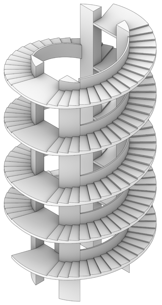
The helical staircases are placed between the columns and the façade of the tower. Each staircase has a width of 1.80 m and a variable height depending on the distance between two consecutive floors (1.40 m – 1.95 m – 1.70 m). The remaining space hosts the landings. The railings, 90 cm high, are modeled along the staircases.
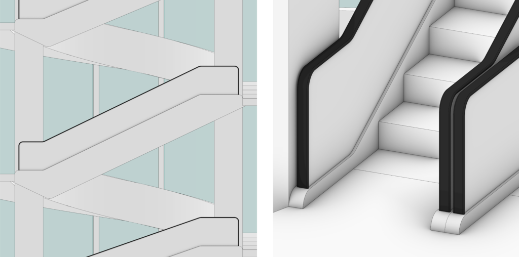
The escalators were not drawn in the elevation and section drawings by Sacripanti. We only know their width, 90 cm, and their heights, the same as the staircases. Each escalator has been modeled with a structure (in which are placed the steps and the motion mechanism), an opaque panel, and a handrail. The structures and the panels are simple extrusions of profile curves; the steps are modeled as boxes, through the Rhino command Box; each handrail is modeled with the Rhino command Sweep 1, using the profile of the panels as rail and a simple rectangle as section. The edges of the handrail are then rounded through the Rhino command Fillet Edge.
According to the original drawings, we can then modify the entrances and at the accesses to the various floors of the towers by adding doors, curved beams and additional walls.
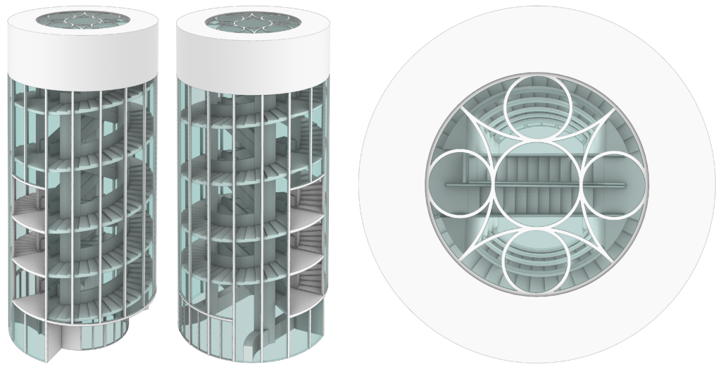
Referring to the Rhino blocks logic, we have modeled 46 blocks instead of 422 different elements, reducing substantially the size of the model through the use of instances.
Step 2 – Pillars
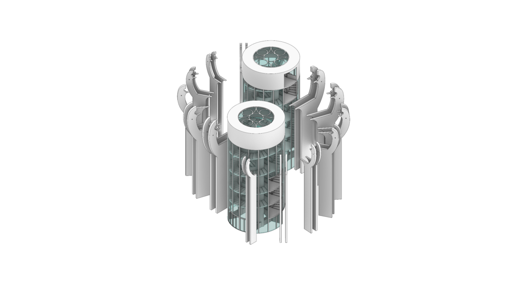
The pillars are modeled as simple extrusions. The profiles of the seven types of pillars have been extracted from the original drawings, as well as their positions. At a height of 14.40 m, to each pillar has been added a circular hole for the positioning of the pivots for the connection with the blades. Collectively we have modeled seven blocks, instead of 28 different elements.
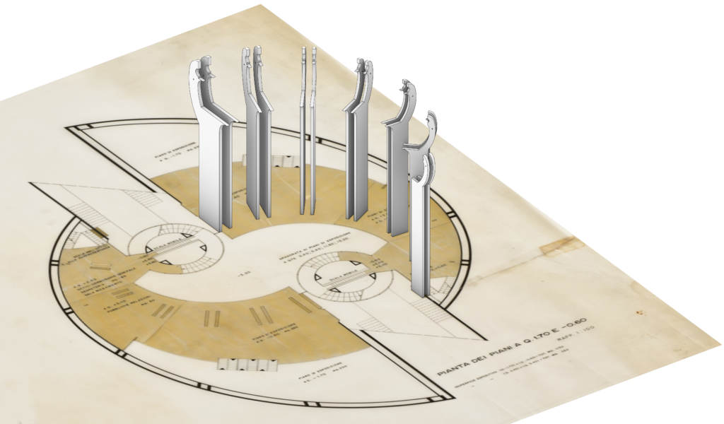
Step 3 – Blades
Each blade is generated from two eccentric vertical circumferences, having different radii. The centers of all the circumferences, and thus the centroids of all the blades, are planar and placed at a height of +14.40 m. The table of the dimensions of the blades can be found in the original technical report of the project, while their positions are obtained from the technical drawings.
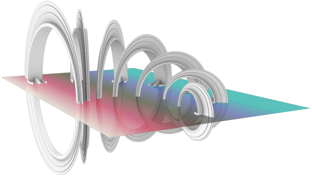
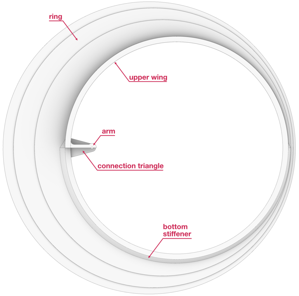
The modeling of each blade consists of 5 elements: the vertical ring, the upper wing, the bottom reinforcement, the arms, and the triangle that connects the blade with the pillars.
- The vertical ring is composed by the two edge circumferences and it does not always have the same thickness but increases and decreases in with. The main faces of each ring can be modeled using the Rhino command Planar Surface, while the thicknesses are obtained through the extrusions of the edges.
- The profile of the upper wing retraces the profile of the upper semi-circumference of the ring, and it is drawn with the Rhino command Offset. The thicknesses of the wings decrease from the largest to the smallest blade. The width of each wing narrows down from the outside to the inside of the pavilion.
- The bottom reinforcement profile is modeled through an offset of the bottom semi-circumference of the ring and by adding two triangles at the extremes of this last curve.
- The arms are modeled through the extrusion of closed curves.
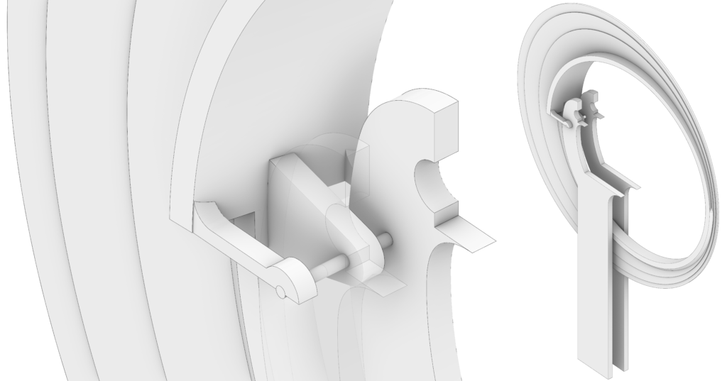
- Each triangle aimed at connecting the blades and the pillars is modeled as the extrusion of a rounded triangle with a hole for the pivot. The angle generated by each triangle has been drawn from a technical drawing, courtesy of the Prof. Maurizio Dècina.
Finally, the blades are placed between the corresponding couple of pillars, connecting them by sleeves, which are modeled through the Rhino command Cylinder.
Referring to the blades, the use of Rhino blocks allows for limiting the size of the model, modeling seven blocks instead of 14 elements.
Step 4 – Mantle
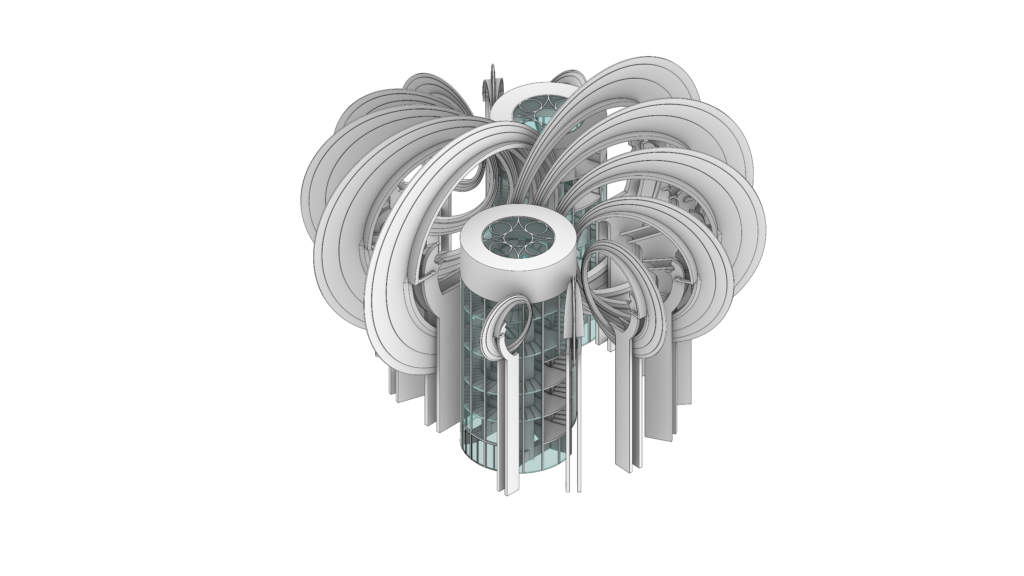
The modeling of the mantle has been conducted with the software Grasshopper and the physics engine Kangaroo, in order to simulate the behavior of a membrane. The procedure can be laid out as follows:
- The first step of the Grasshopper definition consists in importing the seven blades into Grasshopper using a Brep component.
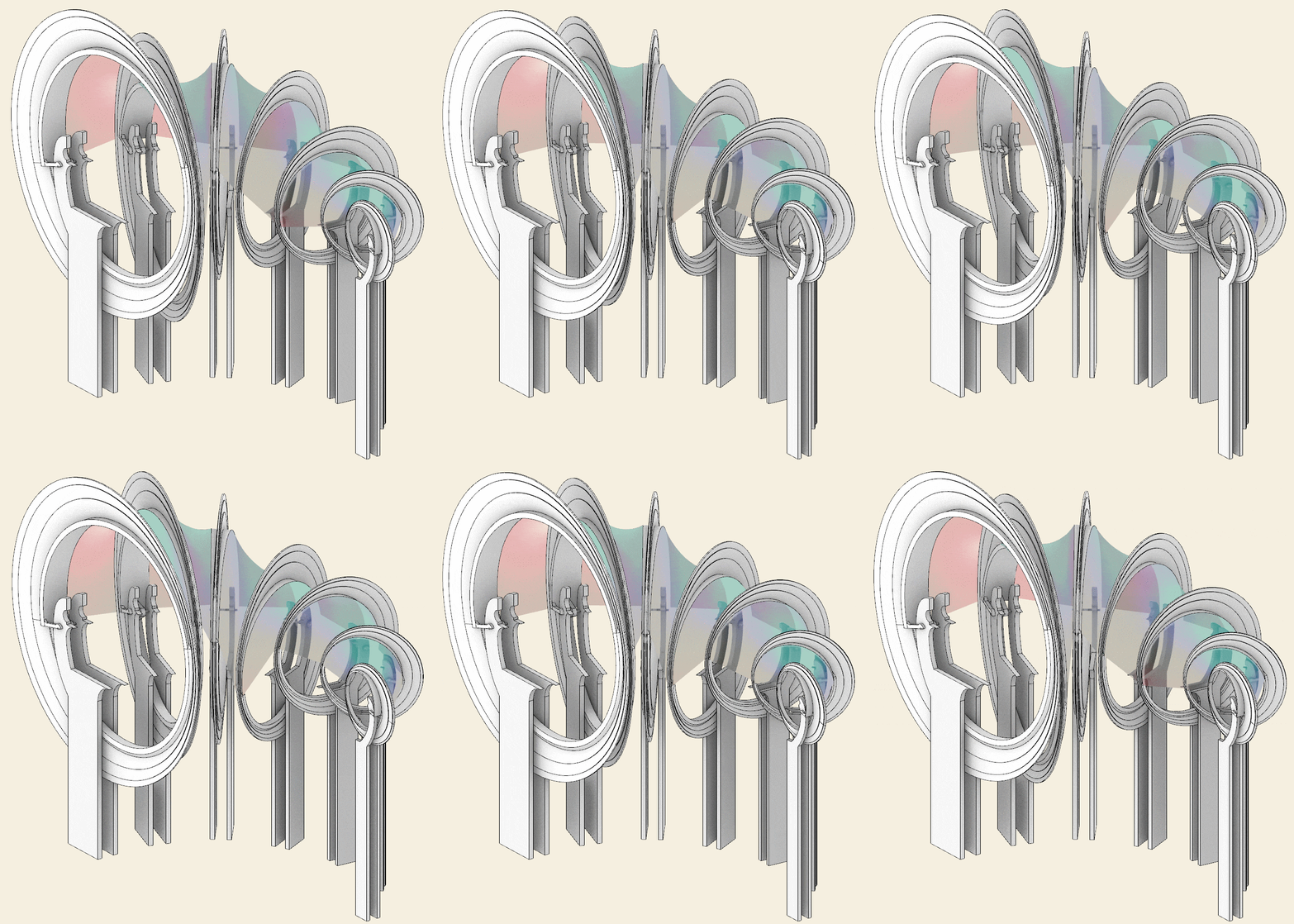
- The second step is to rotate each blade using the sleeves as pivots through the Rotate Axis component, which requires three inputs: the geometry (or the geometries) that needs to be rotated, which are the blades; the rotation angle – a variable parameter; and the axes of the rotations, which are the axes of our sleeves. Since the blades should swing randomly and independently of one another, we can use 14 Graph Mapper components to manage the rotation values. With a unique Number Slider set from 0 to 1 we can rotate each blade following the path of each correspondent graph mapper. The values coming from the graph mappers are then remapped with the Remap Numbers component using [-18°; +18°] as target angular domain for the four biggest blades and [-15°; +15°] for the others. Operating on the Grasshopper data tree, each blade corresponds to one rotation angle and one rotation axis.
*Notice that, for our VR experience, the final simulation of the random motions of the blades has been programmed in Unity via a script.
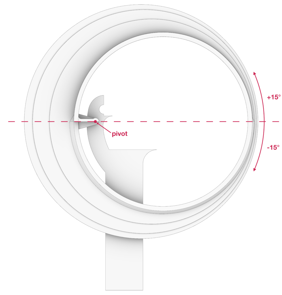
- The next step is the generation of the ruled surfaces between the blades. To do that we need to extract the top-outer edges of the wings of the blades, on which the mantle will be hooked, using the Brep Edges component combined with the List Item component. Then the edges are divided in a certain number of segments through the Divide Curve component, detecting n +1 points on each edge. Connecting with the Line component the corresponding points of two consecutive blades, we get the main curves of the ruled surfaces which can be generated through the Loft component. Rotating the blades, the ruled surfaces will twist and adapt.
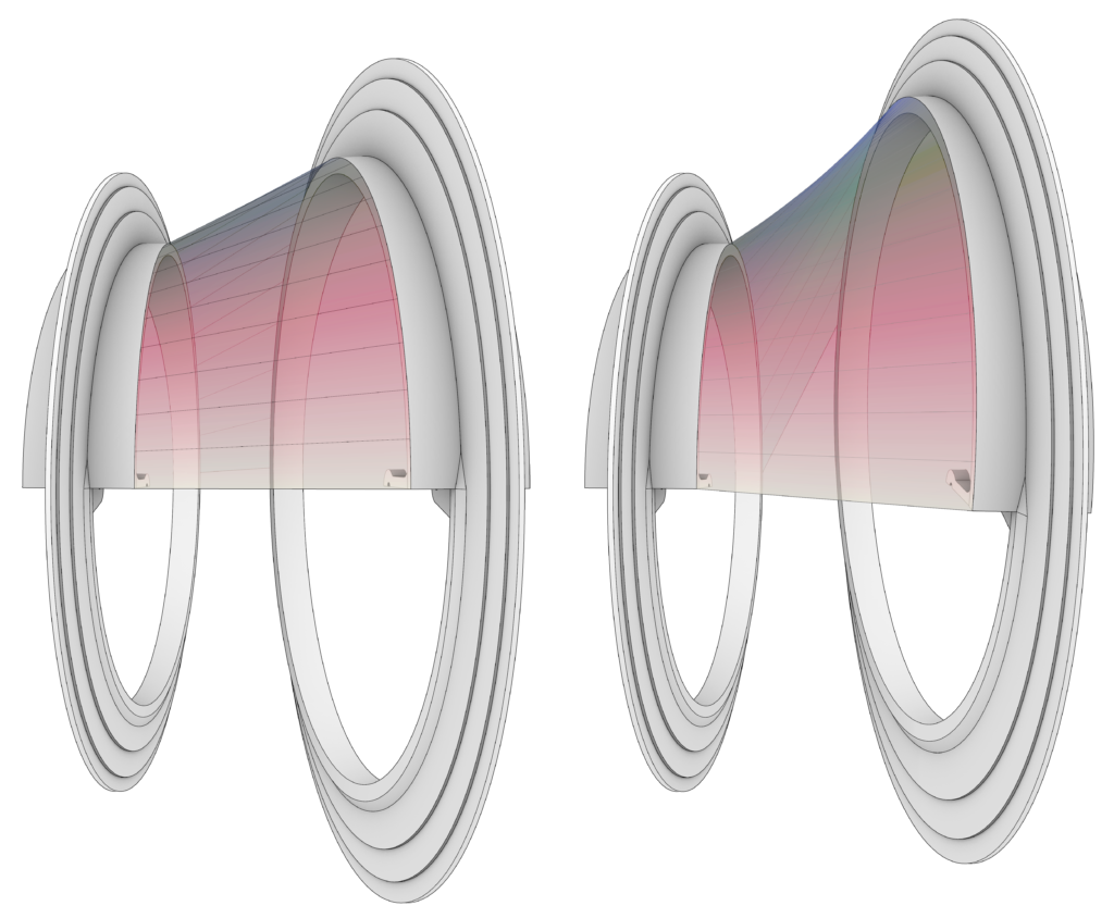
- The last step of the process is the simulation of the elastic behavior of the mantle using Kangaroo. To do that, we need to convert the ruled surfaces into meshes using the Mesh Surface component. Those meshes are then decomposed into the main elements for the springs-particles simulation which are: 1) the anchor points of the membrane (the naked vertices of the meshes) extractable with the Kangaroo’s component Naked Vertices; 2) the particles (the vertices of the meshes) extractable through the Vertices component of the plugin Weaverbird and 3) the springs (the edges of the meshes) extractable through the Weaverbird’s component Mesh Edges. The vertices of the meshes can be converted into particles using the Kangaroo’s component Unary Force and by setting a negative Z vector as force input. The edges of the meshes can be converted into springs using the Kangaroo’s component Springs From Lines by setting the values of the rest length equal to the length of each edge multiplied by a factor between 0 and 1. In this way we can boost or mitigate the membrane behavior. For our simulation we used a value of 0.90. The membrane simulation is obtained connecting the anchor points, the particles, and the springs into the Kangaroo Physics component.
- Varying the value of the number slider that manages the rotation of all the blades, each membrane portion can adapt itself to the movement of each blade in a dynamic and responsive way.

Step 5 – Spiral base
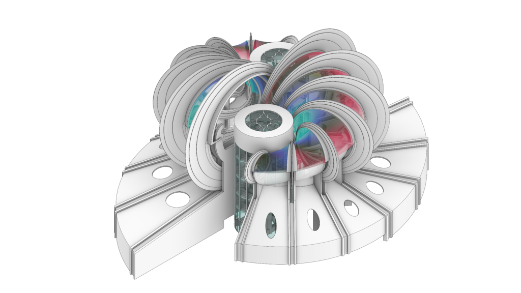
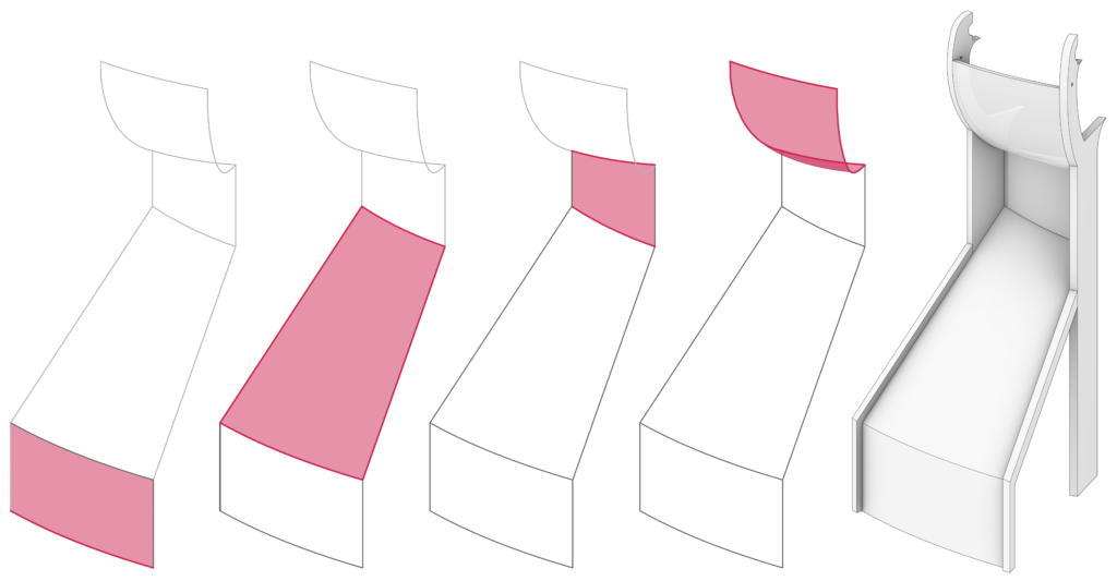
Each side of the spiral base of the pavilion is composed of six slices bounded by the pillars and by a set of beams connected to these pillars. These beams are modeled as simple extrusions.
Each slice is composed of a combination of geometries that, from bottom to top, first follow the beams and then the pillars (as shown in the figure below). These geometries are modeled with several Rhino commands: Extrude Curve, Sweep 2, and Loft.
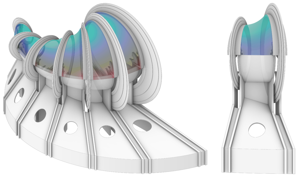
The slices of the base have a thickness of 20 cm. The oblique parts of the slices are perforated by a set of cylinders having decreasing radii and placed along a spiral curve. The resulting holes are filled with windows having frames 10 cm thick, modeled through the Rhino command Offset Surface. The glasses are modeled as surfaces from planar curves. The spaces between the couples of pillars are filled with an ideal continuation of the spiral base.
Step 6 – Slabs
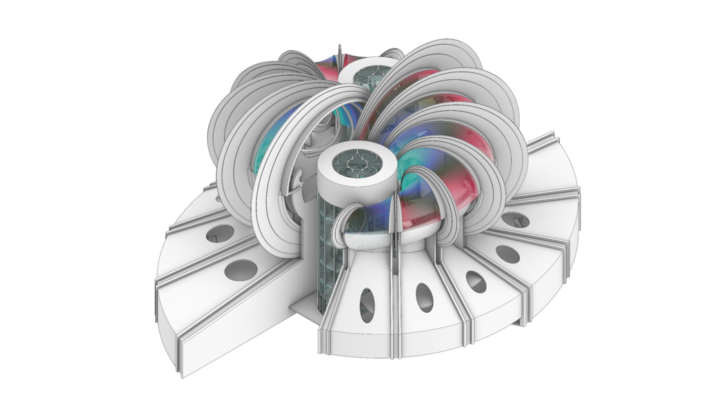
The slabs of the two last exhibition floors are generated from the intersection between four eccentric circumferences and a diagonal corridor. The resulting shapes are extruded by 20 cm. The final shape of the slabs is obtained through a Boolean Difference between the slabs and the pillars.
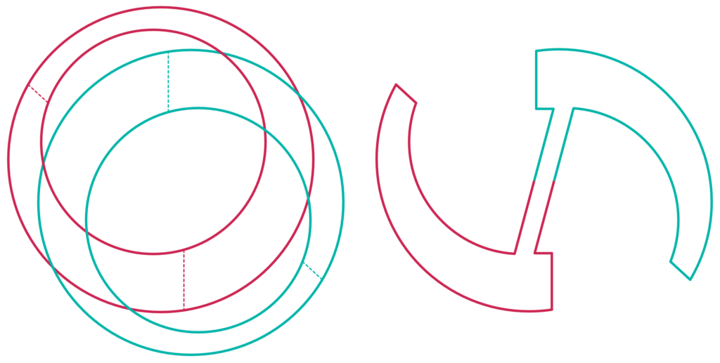
The remaining slabs are modeled from the drawings of the pavilion and they are also extruded by 20 cm and then subjected to a Boolean Difference with the other components of the pavilion.
Step 7 – Pneumatic system
The pneumatic system, aimed at moving the blades, consists of six main elements:
- The pneumatic cylinder, whose modeling is based on an original technical drawing. The external part of each cylinder has a hole aimed at hosting the pivots that allows for the movements of the cylinders.
- The piston which is modeled as a simple cylinder with a plunger at the end. The length of each piston, as well as the pneumatic cylinders, depends on the dimension and the excursion of the blades.
- The cables of the compressed air, two for each pneumatic system, are modeled with the Rhino command Pipe.
- The support of the pneumatic cylinder is modeled as a couple of triangles with a rounded angle. Each triangle has a hole for the pivot.
- The support is connected to the slab with a rectangular plate, having rounded edges, and through four bolts.
- A second rectangular plate with a semi sphere is welded on each blade in order to simulate the spherical joint that connects each blade with the corresponding piston. The plate guarantees the orthogonality between the piston and the wing of the blade.
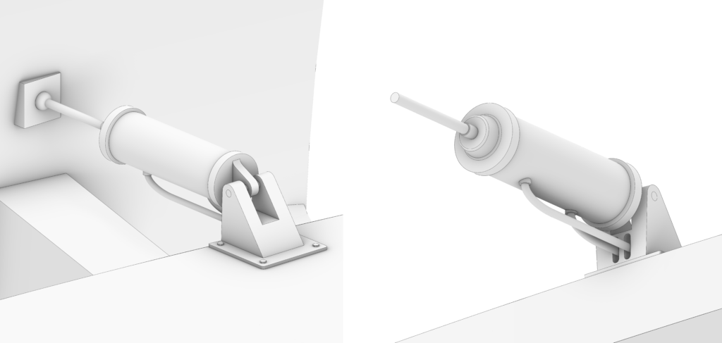
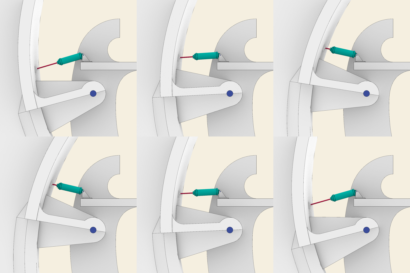
The behavior of the pneumatic system has been simulated in Grasshopper. The same simulation has been applied for the VR experience, directly in Unity. The procedure to simulate the pneumatic system is very simple:
- The second plate is welded to the blade so it rotates with it. The piston should be attached to the centroid of the sphere of the plate, so it rotates likewise.
- The cylinder and the cables rotate around the axis of the pivot passing through the triangular supports. Instead of using Rotate Axis, we can use the Orient Direction component in such a way that the cylinder always “looks” at the sphere of the plate.
- The last step is to orient the piston in the same direction as the pneumatic cylinder using Orient Direction again. This step is aimed at simulating the behavior of the spherical joint between the piston and the plate.
Final step – Details
The last elements that we have integrated in the pavilion are:
- The railings of the slabs, which are generated through the offset of the perimeters of the slabs and then extruded by 90 cm.
- The external platform, modeled from a technical drawing available at the online archive of the Fondo Sacripanti.
- The internal stairs, modeled from the drawings of the pavilion.
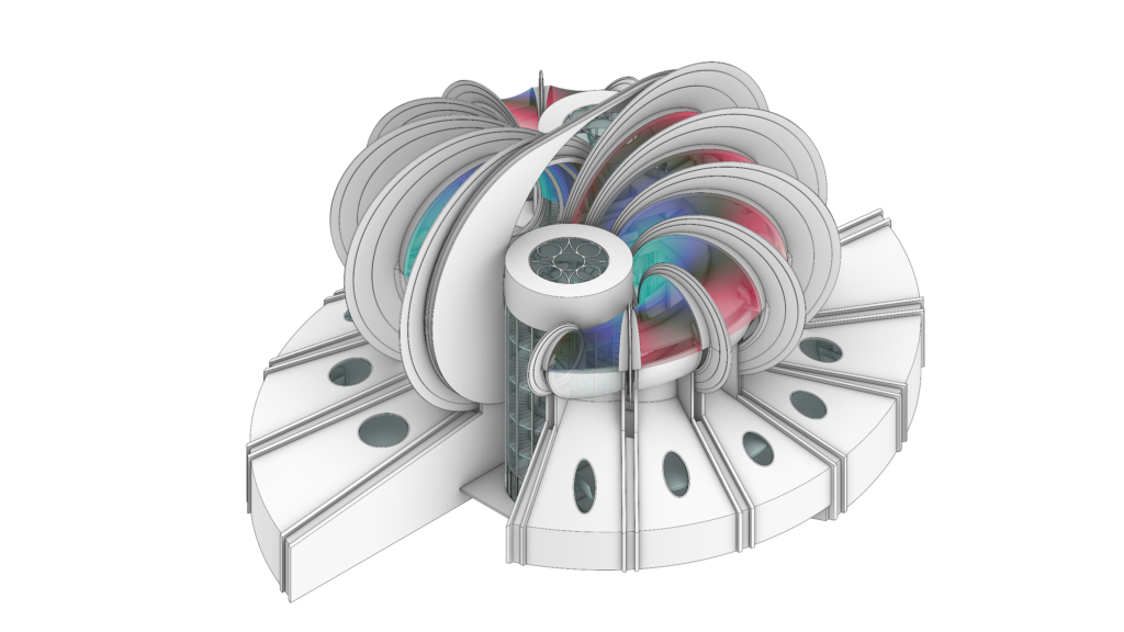
- The steel structure that connects the two sides of the pavilion which has been interpreted from the original physical model.
Below you can find the steps of the 3D modeling process, which are useful for summarizing the elements that make up the pavilion.
Cover image
Rendered model of the Osaka pavilion, T.E.A.M.

